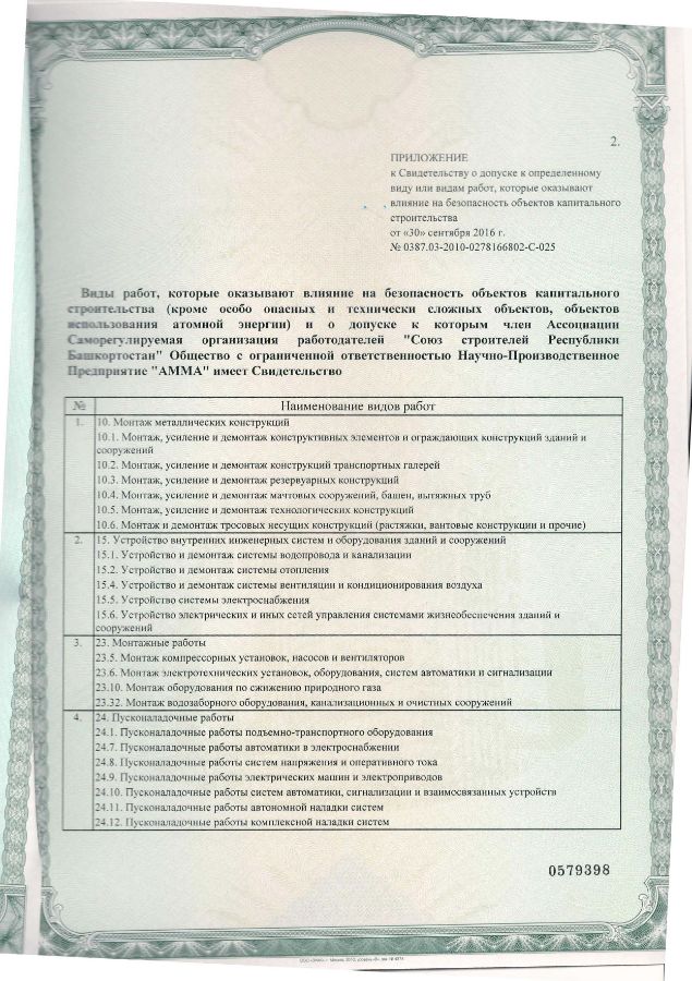
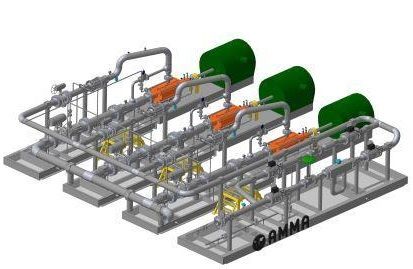
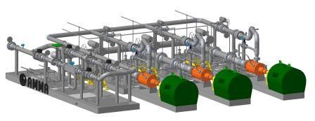
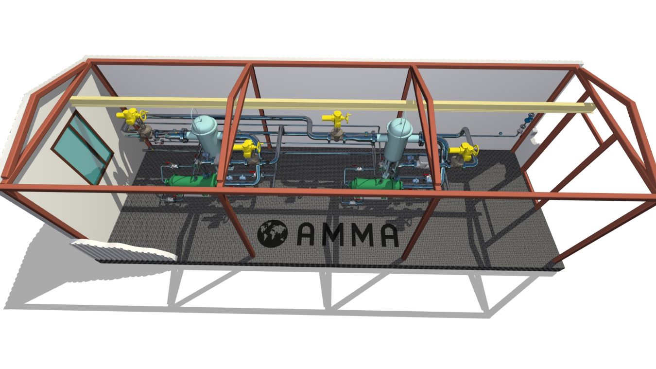
НС-АММА Packaged Modular Pumping Station НС-АММА
Насосная станция питьевого водоснабжения НС-АММА

DESCRIPTION
The НС-АММА Pumping Station belongs to category III according to the degree of water supply security. The building fire hazard category is D. The entrance door is equipped with a light panel 'Water Pumping Station'. The entrance door is equipped with a light panel 'Water Pumping Station'.
The NS-АММА station operates in automatic mode, without constant attendance of service personnel. Local control of all pumps is also provided.
The НС-АММА station operates in automatic mode, without constant attendance of service personnel. Local control of all pumps is also provided. Maintenance platforms are provided for easy maintenance of the pump units.
КОНСТРУКЦИЯ
Металлоконструкции изготавливаются в соответствии с требованиями ГОСТ 23118-99 «Конструкции стальные строительные» и СП 53-101-98 «Изготовление и контроль качества стальных строительных конструкций».
Несущие конструкции и трубопроводы подвергаются антикоррозионной обработке.
В качестве стеновых и кровельных ограждений блок-боксов применяются трехслойные металлические сэндвич-панели с утеплителем.
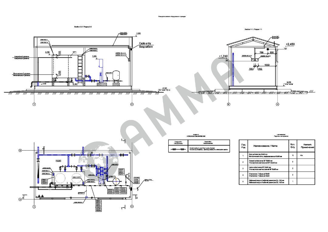
Габаритные размеры блок-бокса выбираются в зависимости от количества, габаритных размеров насосных агрегатов и наличия другого технологического оборудования.
Предусмотрена возможность проведения ревизии, ремонта или модернизации насосной станции.
ОБЪЕМ ПОСТАВКИ
В объем поставки насосной станции питьевого водоснабжения НС-АММА входит:
- насосная станция полной заводской готовности с системами отопления, вентиляции, освещения, заземления, приборами КИПиА, средствами малой механизации;
- металлоконструкции и расходные материалы для монтажа;
- комплект запасных частей и материалов на гарантийный период;
- техническая документация (Паспорт, Эксплуатационная документация).

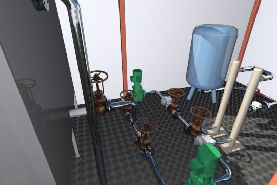
The НС-АММА Pumping Station complies with the requirements of ПБ 08-624-03.. Обвязку в блоке выполняется с возможностью свободного доступа для ремонта при эксплуатации, предусмотрены проходы с антискользящим покрытием шириной не менее 1,0 м между выступающими частями арматуры, трубопровода и т. д., при высоте размещения (приводы, штурвалы и т. д.) более 1,6 м предусмотрены площадки обслуживания.
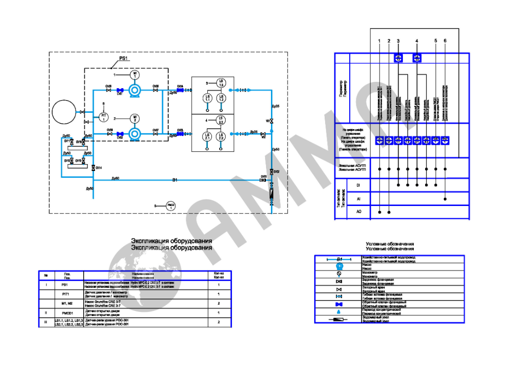
Забор воды на питьевые нужды из проектируемого бака запаса воды, который состоит из 2-х секций. При достижения нижнего уровня воды, насосы в баке отключаются.
Сигнал о достижения аварийного уровня воды передается в операторную.
В трубопроводной обвязке блока предусмотрены обтюраторы для проведения гидроиспытаний.
На время транспортировки и хранения предусматриваются заглушки на концах трубопроводов для исключения попадания внутрь осадков и посторонних предметов.
Размещение запорной арматуры на всасывающих и напорных трубопроводах обеспечивает возможность замены или ремонта любого из насосов, обратных клапанов и основной запорной арматуры, а также проверки характеристик насосов без нарушения требований по обеспеченности подачи воды.
Для учета расхода воды на вводе водопровода предусмотрен счетчик воды.
Арматура в трубопроводной обвязке предусмотрена по классу герметичности А по ГОСТ Р 54808-2011, исполнения ХЛ1 по ГОСТ 15150-69..
Измерительные устройства поставляются с монтажными катушками в комплекте с ответными фланцами, прокладками и крепёжными изделиями в соответствии требованиям СА 03-005-07 «Технологические трубопроводы нефтеперерабатывающей, нефтехимической и химической промышленности. Требования к устройству и эксплуатации» п. 8.1.6.
В комплект поставки включены ответные фланцы с прокладками и крепежными деталями на выходных и входных коллекторах. Материал присоединяемых трубопроводов – сталь 09Г2С.
Насосная станция НС-АММА оборудована первичными средствами пожаротушения.
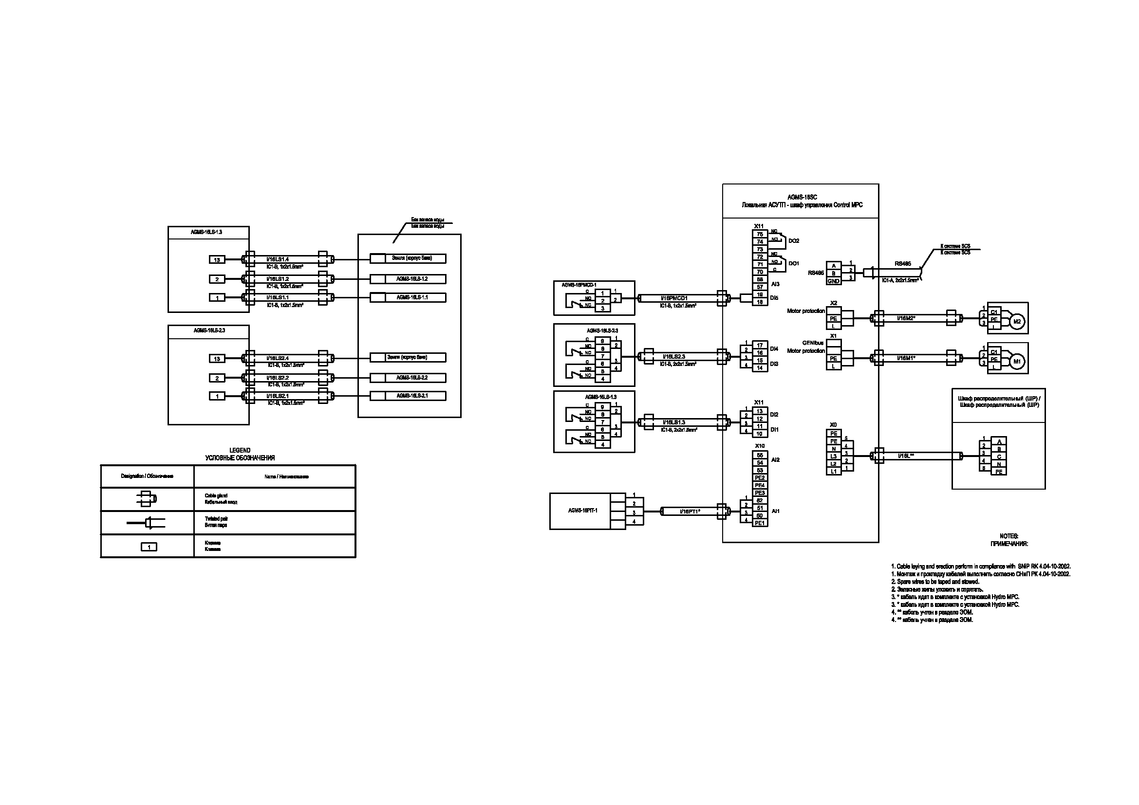
The AMMA-NS-Control Automation System allows remote and manual local control of pumps, fans and gate valves.
AMMA-NS-Control Control Cabinet
It is used for local and remote control of Pump Units.
The НС-АММА Fire Pumping Station is operating in automatic mode, without permanent attendants. Local control of all pumps is provided as well.
Switching on the operating pump is caused by a pressure drop in the outdoor network of the B1 household and drinking water supply. If the operating pump does not turn on, the standby pump will automatically turn on.
The pumps are interlocked when the water level in the tank is low.
Control Cabinet Description
The AMMA control cabinet is a pump control system designed to monitor and control pumps (up to six pumps), used to control pressure booster systems or circulating pumps used for pressure boosting, in heating and air conditioning systems.
The НС-АММА Pumping Station maintains the pressure in the set range by switching on/off the required number of pumps. Pump changeover is automatic and depends on load, runtime and technical faults.
At the first start-up, the Control Cabinet shows a 'Start-Up Wizard'. It helps the user to start the system specifically according to its installation. After the Start-Up Wizard program is executed, it will work according to the set requirements and parameters.
The AMMA Control Cabinet includes setting/monitoring of the following functions:
- Set value;
- Warnings and alarms;
- Alarm log where up to 24 alarms and warnings are stored;
- Alternate set values (set up to six alternate values);
- External influence on the set value (measured parameters can influence the set value);
- Data entry for the main sensor (system control parameter selection);
- Clock program (setting the set values as well as the time and day of their activation);
- Min. time between pump start/stop (setting of pause time between pump start/stop);
- Max. number of starts per hour (limit the number of starts/stops per hour);
- Standby pumps (select one or more pumps as standby);
- Forced pump change (setting the pump change so that the pumps work the same number of hours);
- Trial run of the pump (prevents the pump from seizing up, disintegrates the liquid in the pumps and removes air bubbles);
- Pump stop attempt (automatic stop attempts, self-learning, in case of fixed intervals);
- Pump start-up time compensation (compensation for the time it takes for a pump without a frequency converter to reach full load);
- Stop function (stop the last running pump in cases of low flow);
- Operation in emergency mode (pumps continue to operate despite warnings and alarms);
- Setting up digital inputs;
- Setting the analog inputs;
- Setting the digital outputs;
- Set min., max. and user-defined mode;
- Control source (control from CU 351 or via bus connection);
- Dry run protection (selectable with pressure/level switch, pressure sensor or level sensor);
- Min. pressure (minimum pressure control);
- Max. pressure (maximum pressure control);
- External fault (external fault monitoring);
- Limit 1 and 2 exceeded (control of set limit 1 (warnings) and limit 2 (alarms);
- Pump operating point out of operating range (designation of pump operating point out of operating range);
- Display language (display language selection);
- Units of measure displayed on the display (SI or US units);
- Date and time (date and time setting);
- Passwords (setting a password for the Work and/or Settings menus);
- Ethernet connection (control the system from a remote PC);
- GENIbus number (GENIbus number assignment);
- Software status (program version status).
The management system was established in accordance with the following directives:
- Machinery Directive (98/37/EC)
Standards used: EN 809 [2000] and EN 60204-1 [2006].
- EMC Guideline (2004/108/EC)
Conical sockets with K1/2" male thread are used as base construction for pressure, differential pressure and local pressure gauges.
Pressure sensors, temperature sensors and other instrumentation and automation devices shall be installed in places that are convenient for maintenance (service platforms shall be provided, if the sensors are located at heights of more than 2 m).
For all analog sensors the output signal is 4-20 mA+HART.
The control cables laid in the skid are protected against mechanical damage (laid in pipes or galvanized boxes).
Отопление и вентиляция выполняется в соответствии с нормами на проектирование санитарно-технических устройств СНиП 41-01-2003 «Отопление, вентиляция и кондиционирование», ВНТП 3-85 «Нормы технологического проектирования объектов сбора, транспорта, подготовки нефти, газа и воды нефтяных месторождений», СП 5.13130.2009 «Установки пожарной сигнализации и пожаротушения автоматические. Нормы и правила проектирования».
В насосных станциях НС-АММА предусматривается водяное или электрическое отопление.
Предусматривается приточно-вытяжная вентиляция с естественным побуждением. Вытяжка механическая периодического действия и естественная через дефлектор. Приток воздуха неорганизованный.
Воздуховоды выполняются из листовой стали по ГОСТ 19903-74 с нанесением антикоррозионного покрытия.
Монтаж систем отопления и вентиляции производится в соответствии с требованиями СНиП 3.05.01-85 «Внутренние санитарно-технические системы».
Все отопительно-вентиляционное оборудование заземляется с учетом требований ПУЭ.
The electricity supply is of II category of reliability.
The voltage is 380/220V.
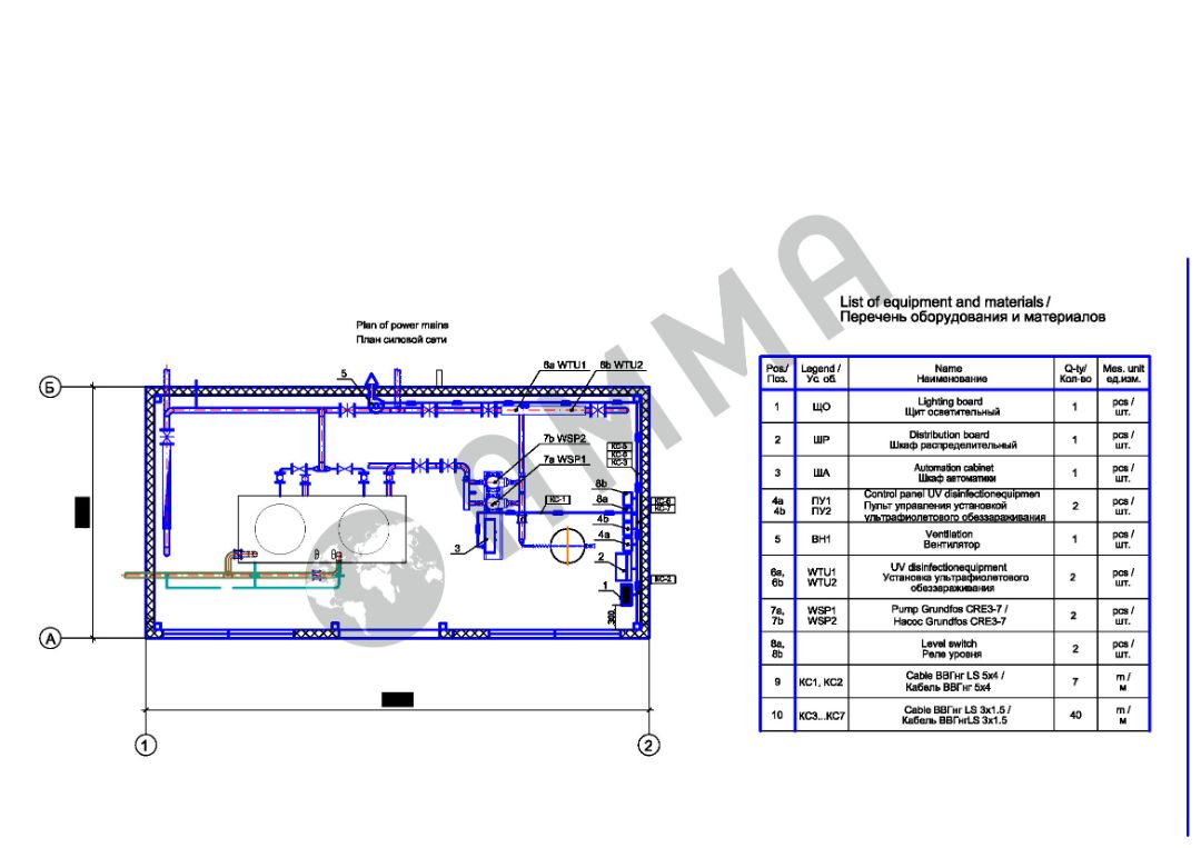
Outside the block (at the rear), terminal boxes are mounted to connect external cables. The number and type of terminals correspond to the number of cores of external cables and the cross sections of the cores.
All power and control connections within the building are carried out in full. Cables with copper conductors and flame-retardant insulation of ВВГнг-LS grade are accepted for laying electrical networks. Three-core cables are used for single-phase receivers.
The power lines have been laid in metal trays. The electrical wiring is protected against overload and short-circuit currents by circuit breakers.
The automatic power-off times for short-circuit currents are in accordance with Table 1.7.1 of EIC.
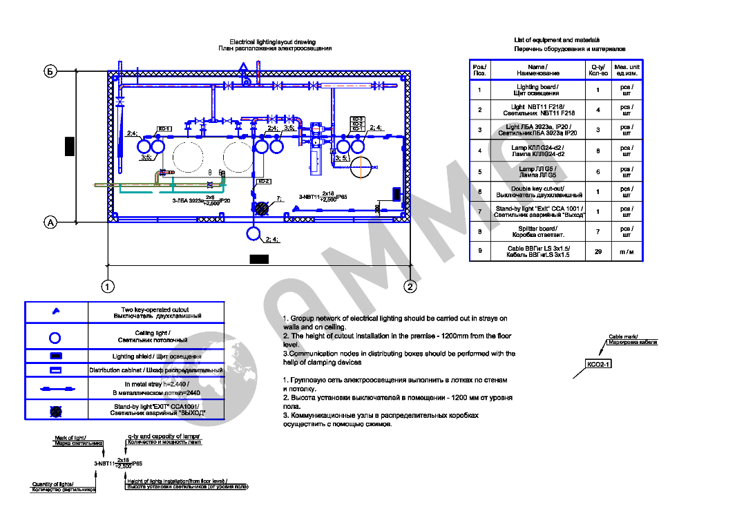
For electrical wiring, cables in a flame-retardant sheath are used. The cross section and the number of cores corresponds to the type of consumers and design load. It ensures the rated tripping time of the circuit breakers at the minimum fault current at the end of the line. Voltage loss on outgoing lines shall not exceed 0.8%. When laying cables, the following are to be separated in accordance with standards: redundant cables, working and emergency lighting groups, power cables and control cables.
Inside the unit, there is 220 V work lighting, 220 V emergency lighting and 12 V maintenance lighting sockets. Part of the emergency lighting lamps are automatically switched to an integrated or dedicated uninterruptible power supply. External lighting of entrances is provided. The type, number and placement of lamps ensures the rated level of illumination according to SNiP 23-05-95, including where manual fire detectors are installed and at a radius of at least 5 m adjacent to the entrances.
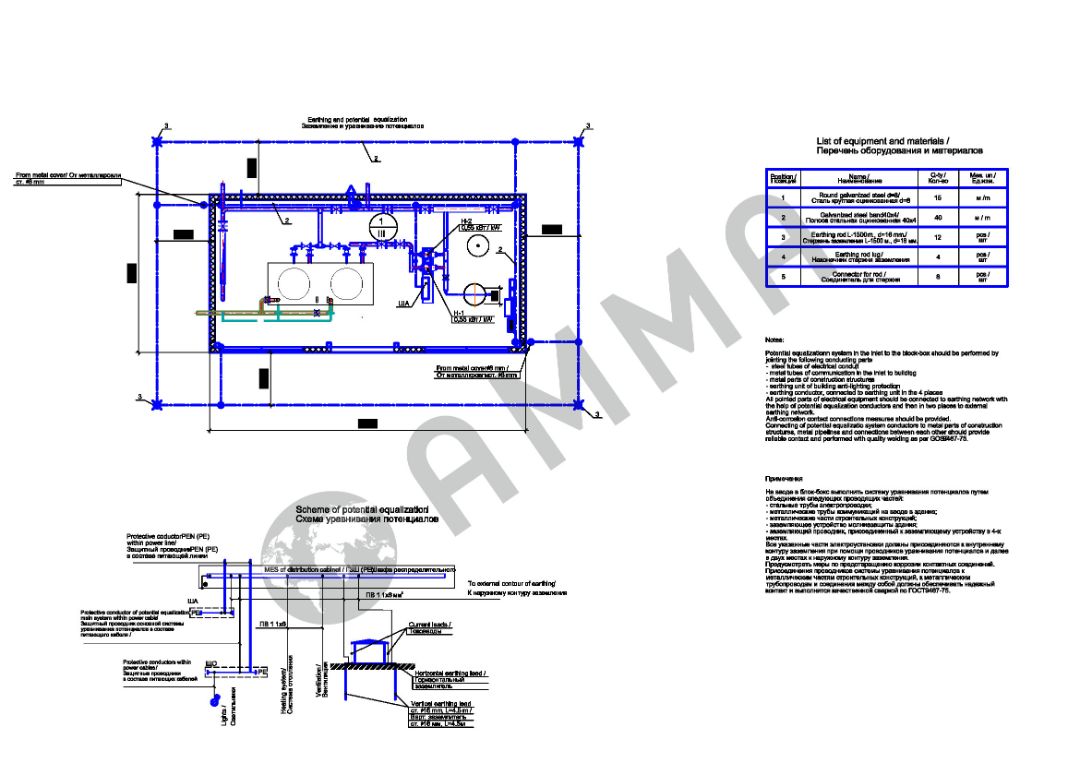
Grounding corresponds TN-S system. Nodes are provided in 2 opposite places for connecting the metal frame of the building to an external grounding conductor.
The block's metal frame and the roofing material have characteristics that ensure their use as lightning arrestors and current conductors. Special constructions for lightning protection are provided as well.
Electrical equipment, control equipment, wiring and earthing networks shall be selected and mounted in accordance with current regulations and operating conditions. All materials and electrical equipment shall have a certificate of conformity and approval from the Federal Environmental, Industrial and Nuclear Supervision Service.
The earthing connection is made along the perimeter of the pump station at a depth of 0,7 m from the ground levelling and at a distance of 1 m from the foundation. Steel rods 16 mm in diameter and 4.5 m long are used as vertical earth electrodes, while a 40x4 mm steel strip is used as horizontal earth electrode. The horizontal and vertical earth electrodes are connected by welding. The welding points are protected against corrosion. The earth electrode trench shall be backfilled with homogenous soil free of stones, crushed stones and debris. Backfilling is done by tamping down the soil.
To protect against electric shock in the event of a faulty insulation, the following protection measures apply in the event of an indirect contact:
- equipotential bonding;
- automatic power-off.
A basic equipotential bonding system is carried out in the building, connecting the following conductive parts:
- PEN conductor of the supply line;
- the earthing conductor connected to the earthing switch;
- metal pipes of utilities entering the building;
- metal parts of the building frame;
- an external lightning protection system.
For connection to the main equipotential bonding system, all these parts are connected to the Main Grounding Bus (MGB) by means of equipotential bonding conductors.
В качестве проводников уравнивания потенциалов используются специально прокладываемые проводники, а также металлические строительные конструкции, отвечающие требованиям к проводимости и непрерывности электрической сети.
All project and operational documentation is available in Russian. If necessary, all technical, project documentation can be translated into any other language.
The following technical documentation is supplied with the NS-АММА Pumping Station:
- datasheet, operating manual for the NS-AMMA pumping station;
- copies of the datasheets for all technical devices included in the pumping station;
- specification, assembly drawing and assembly drawings of the component parts;
- acceptance report;
- certificate of compliance with the NS-AMMA technical regulations.

Погрузка насосной станции НС-АММА на транспортное средство должно производиться крановыми средствами соответствующей грузоподъемности, снабженными траверсами и чалочными устройствами.
Подъем насосной станции НС-АММА разрешается только за предусмотренные для этого элементы.
Подъем насосной станции НС-АММА другими способами запрещается.
Крепление насосной станции НС-АММА к транспортным средствам должно производиться по техническим условиям погрузки и крепления грузов для каждого вида транспорта.
Габаритные размеры насосной станции НС-АММА соответствуют требованиям габаритов погрузки «Техническим условиям погрузки и крепления груза» МПС России.
When ordering AMMA equipment and buildings, carefully analyse the slinging requirements. If you choose equipment with bottom slinging, make sure that the unloading and reloading point has lifting beams for our products. Together with our products, you can always order the TR-AMMA beams for safe unloading, loading.
During the journey, AMMA equipment can be reloaded from road to rail, from rail to sea, from sea to road again, etc.
For safe, convenient delivery of AMMA equipment, we recommend you to order TR-AMMA beams together with our equipment to minimize the potential risks of damage to the equipment during transport.
Лист технических данных на траверсу для подъема продукции Скачать
АММА гарантирует соответствие насосной станции питьевого водоснабжения НС-АММА технической документации при соблюдении потребителем условий транспортирования, хранения, монтажа и эксплуатации.
Гарантийный срок эксплуатации — 12 (двенадцать) месяцев с даты установки или 18 месяцев с даты поставки в зависимости от того, который срок наступит раньше. Срок эксплуатации насосной станции НС-АММА 8 лет.
Гарантийные сроки примененных в насосной станции НС-АММА комплектующих изделий установлены заводами-изготовителями этих изделий, которые несут ответственность за их качество.
Гарантийный срок может быть согласован с Заказчиком.